4-wire Conventional Smoke Detector with Relay output 12v/24v smoke alarm Conventional Smoke Detector
BEFORE INSTALLING
NOTICE:This manual should be left with the owner/user of this equipment.
IMPORTANT:The detector must be tested and maintained regularly following the proper authorities’ requirements. The detector should be cleaned at least once a year.
1. GENERAL DESCRIPTION
The detectors are photo-electronic detector uses a state of-the-art optical sensing chamber. This detector is designed to provide open area protection and to be used with most security alarm control panel.
Two LEDs on each detector provide local 360° visible alarm indication. They flash every 5-6 seconds indicating that power is applied and the detector is working properly. The LEDs latch on in alarm,will be off when a trouble condition exists indicating that the detector sensitivity is outside the listed limit. The detector can be restored to normal status automatically when the ambient smoke or temperature below the alarm value.
2. SPECIFICATIONS
Operating Voltage Range: 9 to 28 VDC Volts Non-polarized
Standby Current: ≤200µA
Maximum Alarm Current (LED on): ≤45mA
Alarm Relay Contact Ratings: 1A@ 24V DC
Operating Humidity Range: ≤95%RH(40°C±2°C) Relative Humidity, Non-condensing
Operating Temperature Range: -10°C to 50°C (14°F to 122°F)
Smoke Alarm Sensitivity: 0.15~0.3dB/m
Height: 55 mm installed in Base
Diameter: 103 mm
INSTALL THE DETECTOR BASE
1. Open area smoke or heat detectors are intended for mounting on a ceiling or a wall in accordance with the fire standard in your country.
2. Attach mounting base to ceiling or wall. The base of the detector can be mounted directly onto an electrical junction box such as an octagonal (75mm, 90mm or 100mm), a round (75mm), or a square (100mm) box without using any type of mechanical adapter.
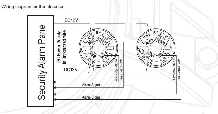
3. Position all wires flat against terminals, and fasten the wires on the terminals, See Figure 1.
4. Terminals function description:
Terminal 1: Relay Output -COM
Terminal 2: Relay Output – NO/NC (default NO)
Terminal 3: DC Power –
Terminal 4: DC Power +
INSTALL THE DETECTOR HEAD
1. Align detector head alignment mark line with the base’s start alignment mark line as shown in Figure 2
2. Push the detector head into the base while turning it clockwise to secure it in place.
3. Do not install the detector head until the area is thoroughly cleaned of construction debris, dusts, etc.
4. After all detectors have been installed, apply power to the control panel.
5. Test the detector(s) as described in the TESTING section of this manual.
6. Notify the proper authorities that the system is in operation.
ADJUSTING THE RELAY FOR NO/NC
The default condition for the relay is “normally open” (NO).
1. To adjust the normal condition of the relay to “normally closed” (NC), use a flat head screwdriver to open the detector head form the bottom.
2. There is a jumper head next to the relay on the PCB. Remove the jumper head and reinsert it in the NC position.
3. Carefully reinstall the head front cover.


